Visualizzazione post con etichetta sdr. Mostra tutti i post

giovedì 5 maggio 2022

Shiva2 DX Cluster for SWL / BCL

A new completely rewritten version of the original shiva dx cluster

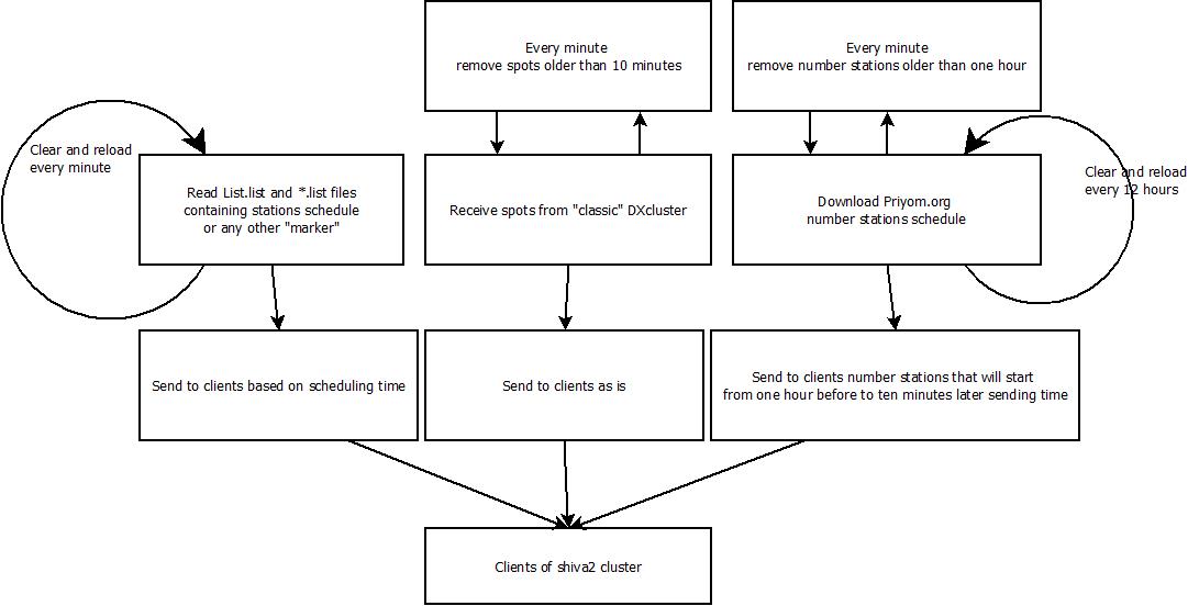
Shiva2 DX Cluster connects to a “classic” ham radio dx cluster and repeat the dx spot to shiva2 clients while adding other spots based on HFCC data files and Priyom.org number station schedules.

It is intended to use with SDR Console for SWL/BCL so they are able to see broadcasting stations, for example, based on scheduling day and time, spots of ham radio operators, fixed markers about CB or PRM channels, or hf beacons, number stations based on their schedule and so on. Priyom.org number stations are sent for 1 hour since the start of transmission.


See how it works on SDR Console :


Check my github page here:
https://github.com/IU2MEH/shiva2


If you want to access my shiva cluster already running h24,
please contact me commenting below or with contact form here in the right
I will give you user and password if:
- you contribute to this project improving the code
- you contribute in another way like sending me a list or improving documentation or something like 
- you send me little money via paypal to help to cover my server costs

venerdì 24 gennaio 2020

Kenwood TS-480 SAT panadapter interface - part 2


We will see how to configure sdr-console ( but the same can be done with other similar softwares ) to create a panadapter interface.
First follow this article : Kenwood TS-480 SAT panadapter interface - part 1 .
Then we have to take a USB CAT cable that connect the rig serial port to an usb port of out pc.
Search for a non chinese cable, for a cable that use the prolific PL2303 driver.
Once cable is connected and driver installed you will see under device manager of windows a ( new ) COM port as below. Take note of the assigned number, in this case 8 , COM8.

Connect also the SDR dongle as described in "part 1" and open sdr-console.
Add your SDR to the "Definitions", you will find how on the software manual or google, it is very simple.
Then under label "view" click "select" on the right side. Then flag "External radio".

And restart sdr-console as asked.
You will see on the left a new item:

 Click on the question mark, settings will appear, click Omnirig and configure it as below, changing the COM port accordingly with what you have seen in Windows device manager:

Click ok and configure other settings as below:

Click on the "Frequency" label on the left and configure the IF frequency, for TS-480 is 73.095Mhz.
Configure also the offsets, you see below values for the SDR dongle Nooelec Nano3 but I think you have to adjust them in the case you use another dongle.

Click OK.
In my case, under the label "Home" of the main window, AGC is ON and RF Gain is set to 14.4dB, not automatic. If I set more dB or auto mode I see a lot of artifacts and all will become useless.

Now you can see your waterfall plus/minus 100kHz the center frequency, where radio is tuned.
They are also synchronized, when you change frequency or mode on the radio, the same is changed also on sdr-console and vice versa.


Please comment below if there are corrections to be done or something is missed.
Thanks


sabato 10 agosto 2019

AOR AR8000 Panadapter Interface

The following post will describe how to take the IF from the radio scanner AR8000 by AOR and feed it to an SDR, this is useful to see the spectrum around the tuned frequency and/or use sdr sharp and its plugins to decode, for example, TETRA signals.

First you have to open the back of our radio removing the screws marked in the pics below:


Open and find a stripe of 16 pins, you are on the back of the board, see the red circle on the pic below:


Now, the IF output is the 10th pin from the left, the 6th from the right.
Solder a 100pf capacitor to decouple the radio from the sdr and to prevent sdr with bias tee to inject some current.
Add a cable taking the earth from the negative pin of the battery or from other place you like,
and a panel female connector, I choose to use a 2,5mm mono jack, and fix it on one side


You can close the radio now and make a cable to connect the IF out to an SDR, in my case a 2,5mm mono jack male to SMA.
Connect SDR to your PC and open SDR# or other sdr software you like.
According to AOR manuals you have to tune the following IFs, depending on the frequency sintonized:
from 100kHz to 450MHz and from 1500 to 1950MHz IF is at 736,250MHz
from 450 to 1500MHz IF is at 275,450MHz

Below are two examples:

Broadcast FM signals, radio set on 88MHz SDR# on 736,250MHz

TETRA signal, radio set on 463MHz and SDR# on 275,450MHz


sabato 1 giugno 2019

Kenwood TS-480 SAT panadapter interface

A panadapter is a device that connects to a standard hardware radio and allows you to visually see the RF signals on a waterfall. Since SDR’s run on the PC, they naturally have the ability to display a panadapter screen, and most software like SDR#, HDSDR and SDR-Console already provide this. The RTL-SDR can also be used to add panadapter capabilities to a regular hardware radio.

First of all you have to find the IF out pin named CN152 on our rig, opening the case bottom side, near the front.

kenwood ts-480 if pin

kenwood ts-480 if pin

I have found that connector on an old radio, something related to audio/music cassette deck, however they are very common.

Coax cable go out of the rig through the grid on the front panel

Even if with the signal coming out the IF stage we can already feed an sdr, it is strongly recommended to use an adapter to:
  • match impedence
  • don't load the rig uselessly
  • isolate the couple rig-pc
Personally i have bought this Panoramic Adapter Tap (PAT70M)  and put it in a Mentos box


adding a female jack to feed it with the required power, 13,8V , taken from the same power supply of the rtx.
It is not necessary to power off or isolate this board during tx.
On the other side of the box comes out the signal on a coax cable with MCX male plug that will feed our sdr, a NooElec Nano 3

Check here Kenwood TS-480 SAT panadapter interface - part 2 to see how to configure sdr-console.


giovedì 2 maggio 2019

RaspBRadio - A Raspberry Pi and RTL-SDR Based Boombox

Raspberry radio scanner from 0 to 1750MHz

Introduction:
I'm not a python developer, you will find a lot of "strange things" in the code cause it is copy-pasted here and there from the net... but it's working.
Please help improving the code.
Any question or comments will be accepted.
------------------------------------------------------------------
For this project I have used:

SHARP GF-450 H Boombox - only case, antenna, speakers and a red led remain in place
Raspberry Pi 3 Model B
Nooelec Nano 2
Nooelec Ham It Up v1.3 HF upconverter
TDA2822M audio amplifier - DON'T use PAM8403 cause it produces a lot of interference in HF
KY040 rotary switch
4x4 matrix keyboard
4 lines lcd display
i2c level shifter
various cables and connectors
------------------------------------------------------------------
Description:
As you can see from pics below, there are 4 rotary switch on the top of the radio, one, on the left, is the potentiometer directly attached to audio amplifier module that receive audio signal through jack-jack cable connected to raspberry.
Other 3 are the ky040 rotary switches, 1st is to go up and down in freq with 500Hz steps and if pushed decrease the squelch level, 2nd is with 5KHz steps and if pushed change demodulation, 3rd with 50KHz steps and if pushed raise the squelch level.
On the right there is a lever, is connected to the upconverter in the place of the original switch and plus select the antenna, the original stylus for frequency above 30MHz or an external antenna for frequency below 30MHz (when upconverted is turned on) with a BNC connector on the right side of the radio.
On the right side there is also power connector, i've just used original raspberry power adapter with a male-female generic dc plug in the middle of the cable cutted and soldered.
Power must reach raspberry, upconverter and audio amplifier.
On the front we can find the lcd, inside, where was the musicassette mechanics, connected to raspberry gpio through a i2c level shifter; and a 4x4 matrix keyboard.
On the back, just as a backup when wifi doesn't work, there is a rj45 female coming from raspberry.
Audio is also streamed on the network thorugh a vlc instance.
------------------------------------------------------------------
Usage:
use the ky040 to set frequency, squelch and demodulation as described above.
Press 'A' to enter a frequency manually then press '#' to confirm and exit the menu.
Press 'C' to enable upconverter then move on the right the lever switch on the top of the radio.
Press 'C' again to disable and move the lever on the left.
Press 'D' to set audio properties, in this menu you can press 1 or 2 to decrease or raise bass volume, 4 or 5 for middle, 7 or 8 for high, 3 or 6 for software volume, then press '#' to exit.
Press '*' to shutdown the system.
You can listen the audio streamed on the network using VLC and opening the network stream http://ip_address:8010
If you press the ky040 demodulation switch till "spyserver" appear on the display, you can connect to the radio with sdr#.
Open sdr#, set as souce "spy server" and point to spy://ip_address:5555/ ; the ip address of wifi and vpn is also shown on the display.
------------------------------------------------------------------
If you use the integrated wifi module, you will listen some noise coming out the speaker like a tick.
I observe that these ticks are related to the network usage, more bandwidth is used more noise is produced on the speaker. Issue is resolved disabling integrated wifi and using an usb wifi dongle.
------------------------------------------------------------------
Software requirements for running this python script are:
Raspbian OS updated
rtl_udp, rtl-sdr and spyserver ( check https://airspy.com/download/ )
pad4pi python libraries
cvlc from vlc suite
pulseaudio and alsamixer
wifi or lan configured(with or without openvpn) to use sdr# ( https://airspy.com/download/ )remotely.
------------------------------------------------------------------
Install:
Put the python script on /home/pi/RADIO/ directory, naming it ctrl_rtl.py , together with spyserver and spyserver.conf
Run: chmod +x ctrl_rtl.py; chmod +x spyserver
Edit spyserver.conf for your needs
To run it at startup add to /etc/rc.local the line:
su pi -c "sleep 20; nohup /home/pi/RADIO/ctrl_rtl.py &"
------------------------------------------------------------------
TBD:
- CW listening (and decoding? printing it on lcd?)
- RDS decoding when listening to BFM stations
- do something with 'B' key
- date and time display
- improve speed and stability
------------------------------------------------------------------


raspberry ghettoblaster sdr radio scanner

raspberry ghettoblaster sdr radio scannerraspberry ghettoblaster sdr radio scanner


raspberry ghettoblaster sdr radio scanner

raspberry ghettoblaster sdr radio scannerraspberry ghettoblaster sdr radio scannerraspberry ghettoblaster sdr radio scannerraspberry ghettoblaster sdr radio scannerraspberry ghettoblaster sdr radio scanner